

Top Shunt Resistor Choices for Ultimate Precision Current Measurement
2026-07-12
Precision current measurement isn’t just a luxury—it’s a necessity in fields where every milliamp matters. But achieving ultimate accuracy often comes down to one overlooked component: the shunt resistor. With so many options out there, how do you pick the one that won’t compromise your circuit’s performance? Whether you’re tackling battery management, motor control, or power metering, your choice directly impacts noise, drift, and long-term reliability. At Milliohm, we’ve spent years sorting the exceptional from the merely adequate. Here’s a fresh look at the top shunt resistors engineered for real-world precision—and why they might just redefine your next design.
Why Shunt Resistors Define Measurement Accuracy
Shunt resistors sit at the heart of current measurement, turning amperes into a readable voltage drop. Their precision directly dictates how accurately you can gauge power consumption, battery health, or motor performance. A tiny deviation in resistance value—driven by temperature drift or manufacturing tolerance—can cascade into significant errors, especially in low-current or high-precision applications. In essence, the shunt doesn't just sense current; it sets the ceiling for your system's measurement fidelity.
Material choice and thermal behavior often separate a mediocre shunt from a metrology-grade one. Alloys like manganin or constantan offer low temperature coefficients, but even they can't escape self-heating effects under sustained loads. As current flows, the shunt warms, resistance shifts, and the voltage signal drifts away from true proportionality. This thermoelectric dance makes layout and cooling just as critical as the resistor's datasheet specs—poor thermal management can undo a costly, high-precision component.
Beyond the resistor itself, the way you tap the voltage signal defines real-world accuracy. Kelvin sensing, with its four-terminal connection, eliminates lead resistance errors that would otherwise infect the measurement. Even tiny parasitic voltages at junctions of dissimilar metals can introduce microvolt-level offsets, turning a 0.1% shunt into a 1% uncertainty source. Ultimately, the shunt resistor isn't just a passive part; it's a dynamic boundary condition that shapes the entire analog front-end design.
Metal Foil: The Quiet Performer in Drift-Sensitive Circuits
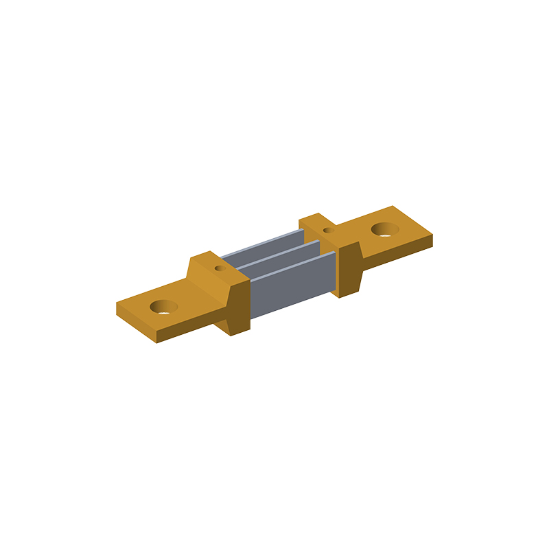
Metal foil resistors often go unnoticed in the shadow of their more exotic cousins, yet they are the unsung heroes when it comes to taming drift in high-precision circuits. Their construction—a thin metal foil bonded to a ceramic core—gives them an almost stubborn resistance to environmental change. This inherent stability means that when your design must hold a voltage reference rock-steady over years of operation, or a voltage divider needs to maintain its ratio through thermal swings, the foil element neither flinches under temperature shifts nor succumbs to the slow aging effects that plague thick-film and wirewound types. It’s the sort of quiet reliability that only reveals its value when a circuit’s long-term accuracy is the deciding factor between a successful product and a field recall.
What sets metal foil apart is its almost invisible immunity to the very stresses that cause other resistors to drift. Bulk metal foil technology distributes strain so evenly that even mechanical stress—whether from board flexing or soldering heat—barely shifts the resistance value. The low temperature coefficient of resistance (TCR) isn’t just a lab-observed number; it’s a practical guarantee that the part will behave identically whether it’s bathed in the heat of a densely packed enclosure or exposed to the chill of an outdoor antenna site. And unlike thin-film resistors, which can suffer from subtle moisture ingress over time, the monolithic foil element remains hermetic, shutting out humidity and its corrosive colleagues. Designers who lean on foil resistors for their reference networks or feedback loops learn to trust them in a way that feels less like component selection and more like architectural certainty.
In the real world, drift-sensitive circuits often hide in plain sight: weigh scales that must hold calibration over a decade, industrial controllers monitoring slow-changing processes, or precision current-sensing in battery management systems where microvolt errors accumulate into maintenance headaches. Metal foil stays unobtrusive, never drawing attention to itself, because it simply does its job without the need for complex compensation algorithms or redundant error-correcting circuitry. It’s the component equivalent of a well-trained watchmaker—quiet, exacting, and endlessly dependable. While no resistor is perfect, the metal foil comes close enough that many engineers consider it the default choice whenever their design whispers the one requirement that matters most: “Don’t change.”
Wirewound Solutions for High-Current Challenges
When currents climb beyond the comfort zone of standard resistors, wirewound designs step in as the go-to solution, not just because they can take the heat, but because their construction naturally spreads it out. A resistive wire coiled around a ceramic or fiberglass core gives these components more surface area to breathe, letting power dissipate without cooking the circuit board. That’s why you’ll find them in braking systems, power supplies, and industrial motor drives—places where a simple chip resistor would pop under the load.
What often gets overlooked is how the choice of wire and winding pattern shapes real-world reliability. Nichrome, constantan, or even custom alloys each bring a different temperature coefficient and corrosion profile to the table, while non-inductive winding styles cancel out magnetic fields that could mess with fast-switching signals. The best designs aren’t just about hitting a resistance value; they balance thermal mass, inductance, and physical size so the part doesn’t become the weakest link when currents surge.
You can see the difference in something like a crowbar circuit or an inrush limiter: a wirewound resistor never gets twitchy when the energy hits hard. It takes the punch and holds steady. That kind of mechanical tenacity embedded right into the wire and the welds comes from a manufacturing ethos that values execution over marketing fluff. If a design demands something that runs hot and doesn’t drift over time, the old-school wirewound still outclasses many newer alternatives.
Thick Film Resistors: Balancing Cost and Consistency
Thick film resistors find their sweet spot in applications where pennies matter but performance cannot slide. They are built by screen-printing a resistive paste onto a ceramic substrate, then firing it at high temperatures. This process is inherently cost-effective, yielding components that can be churned out in huge volumes with machinery that doesn't break the bank. The result is a part that hits a practical balance—decent precision, acceptable noise levels, and reliability that holds up under normal conditions.
Yet the real challenge lies in consistency. Slight variations in paste composition, screen tension, or furnace profiles can nudge resistance values off target. Manufacturers counteract this with laser trimming, a technique that etches the fired film to dial in exact resistances. Even so, thick film resistors typically show wider tolerances and higher temperature coefficients than their thin film cousins. The art is in knowing when that trade-off is worthwhile—for pull-up resistors, voltage dividers in non-critical paths, or any circuit where a ±5% drift won't cause headaches, thick film delivers without draining the budget.
Another layer to the cost-consistency equation is environmental stability. Humidity, thermal cycling, and board flexure can gradually shift a thick film resistor's value. Designers often mitigate these drifts by specifying overmolded or coated parts, or simply by leaving enough headroom in the design. When you weigh the cents saved against the performance gained, thick film resistors remain a compelling choice for the bulk of everyday electronics, proving that smart compromises often lead to the most widely adopted solutions.
Kelvin Connection Layouts That Eliminate Lead Errors
Precision measurements often stumble on the hidden resistance within test leads and contact points. Kelvin connection layouts address this directly by splitting the current path from the voltage sensing path. A four-wire setup ensures that the voltage measurement probes see almost no current, so the voltage drop across the lead resistance is effectively removed from the reading. This simple yet powerful separation keeps the measured value true to the device under test, not the interconnects.
In a physical layout, you see two distinct pairs of traces or wires running to the component terminals. One pair forces the excitation current through the device, while the other pair taps right at the terminal pads to sense the developed voltage. Because the sensing loop draws negligible current, any resistance in those sense leads becomes irrelevant. The real challenge lies in placing the sense points exactly where the current-carrying traces meet the component, otherwise a small but avoidable error creeps back in.
For board-level designs, the technique often manifests as star-connected or split-pad footprints. Each terminal gets a wide trace for current and a narrow trace for voltage sensing, joined only at the pad itself. Differential routing with matched lengths further suppresses pickup and maintains symmetry. When done carefully, this layout technique can reveal resistance values in the micro-ohm range—performance that a standard two-wire connection simply cannot approach without heavy guarding and correction.
Thermal Management Tricks for Long-Term Stability
Keeping electronics cool isn't just about slapping on a bigger heatsink—it's about understanding where the heat actually goes over months and years. One overlooked trick is to deliberately create low-resistance thermal paths away from temperature-sensitive components, using thick copper pours on the PCB even where they aren't electrically necessary. This spreads heat laterally before it ever reaches a fragile capacitor or voltage reference, reducing the slow degradation that thermal cycling causes.
Another subtle technique involves managing airflow at the board level rather than the enclosure. A small baffle, carefully positioned to redirect air across a row of regulators, can drop operating temperatures by ten degrees or more without increasing fan speed—preserving bearing life and keeping acoustic noise in check. Pair this with conformal coating on high-impedance nodes to prevent moisture absorption, and you tackle two silent killers of long-term stability at once.
Finally, don't underestimate the firmware side of thermal management. Intelligent duty cycling of power-hungry peripherals, combined with temperature-dependent clock throttling that kicks in long before critical limits, lets a design gracefully handle unexpected ambient rises. This software-defined margin, when paired with hardware that assumes worst-case dissipation, often makes the difference between a device that drifts out of spec after a year and one that holds its calibration for a decade.
FAQ
It's the heart of the system—converts current into a tiny voltage you can read. Any drift or nonlinearity directly hits your measurement accuracy. Precision shunts keep that conversion stable across temperature and load changes, which is why they're not just any resistor.
Look for ultra-low temperature coefficient (TCR)—below 50 ppm/°C if possible—tight tolerance (0.1% or better), and a low thermal EMF to avoid phantom voltages. Power rating matters too, because self-heating can ruin your readings. Four-terminal Kelvin connections are a game changer for low ohmic values.
Vishay's WSL series is a go-to for many engineers, offering metal strip construction with excellent TCR. Isabellenhütte is legendary for their high-accuracy versions, often found in lab equipment. Riedon and Caddock also have specialist shunts with custom options. Each has its strength depending on your current range and form factor.
A lot—even a 10°C rise can shift resistance enough to throw off a 0.1% measurement if the TCR is high. That's why premium shunts use alloys like manganin or zeranin that barely budge. In the field, you'll see errors pile up fast without low-TCR components.
You can, but you'll fight noise, thermal drift, and lead resistance issues. Standard resistors often have higher TCR and no Kelvin terminals. Purpose-built shunts are optimized for low inductance and predictable behavior—worth the extra cost when accuracy matters.
With two terminals, you're measuring voltage drop across the resistor plus its leads, which adds error—especially below 10 mΩ. Four-terminal shunts separate current path from sense connections, so you measure exactly the voltage across the resistive element. It's essential for micro-ohm-level precision.
It's a balancing act. Too high, and you waste power and generate heat; too low, and your signal gets drowned in noise. Aim for a voltage drop of 50–100 mV at full current to get a solid signal without cooking the shunt. Also, check your ADC's input range.
Forgetting to account for self-heating drift, routing sense traces incorrectly (they should be differential and match impedance), and ignoring thermal EMF at junctions. Also, watch out for the shunt's bandwidth—thick film ones can be inductive, limiting high-frequency measurements.
Conclusion
Achieving precision current measurement starts with the shunt resistor, the quiet foundation that defines accuracy far more than the readout electronics. The drift characteristics of a shunt can make or break a design, and nothing beats metal foil elements when microvolt-level stability matters over wide temperature ranges. Their near-zero TCR and immunity to thermoelectric mismatches keep circuits locked in target, even when ambient conditions wander. For high-current paths that would fry smaller parts, wirewound resistors offer a rugged alternative, turning tens or hundreds of amps into clean, predictable voltages without sacrificing too much precision—provided you respect their inductance and layout constraints.
Beyond the base material, layout and thermal strategy separate a good reading from a noisy guess. Kelvin connections become non-negotiable the moment lead resistance threatens to corrupt your sense lines; four-terminal chip resistors or carefully routed PCB tracks eliminate the parasitic voltage drops that masquerade as signal. Meanwhile, thick film parts fill the middle ground, balancing unit cost with repeatable performance in less demanding points of a system. Their success hinges on thermal management: spreading heat evenly, avoiding hot spots, and derating for long-term drift. When all these choices align—the right element for the dynamic range, the right footprint for self-heating, and a layout that guards the sense path—current measurement turns from an art into a repeatable science, ready for the harshest industrial or automotive environments.
Contact Us
Contact Person: Yuying Gao
Email: [email protected]
Tel/WhatsApp: +86 18926013721
Website: https://en.milliohm.net/